Flashing DIY Frsky 8CH RX - AC810 / F801 … by David HK September 2016
Flashing DIY Frsky 8CH RX - AC810 / F801 … by David HK September
2016

I recently bought the Eachine Tiny QX80 without a receiver
from China Taobao (long story short, Banggood does not delivery items with
battery to Hong Kong, so I need to order from Taobao, but the QX80 in Taobao
only comes with either DSM receiver or no receiver!), and originally I
tried to buy the small Frsky compatible RX from Banggood QX90/QX80 spare parts,
but it was in back order for at least 3 weeks, so I searched Taobao and came
across this KS-Servo AC810 DIY Frsky
RX. This DIY RX is also being sold in
HobbyKing, at around US$12-13 plus shipping.
Also selling in Banggood as "DIY FRSKY 8CH Receiver RX PPM Output For X9D(PLUS) XJT DJTDFT DHT" under US$12, quite a bargain!
Also selling in Banggood as "DIY FRSKY 8CH Receiver RX PPM Output For X9D(PLUS) XJT DJTDFT DHT" under US$12, quite a bargain!
I searched further and came across the below RCgroups discussion link on DIY Frsky TX/RX, which provides the firmware upgrade for this
AC810/F801 (also AC820/F802) DIY Frsky RX.
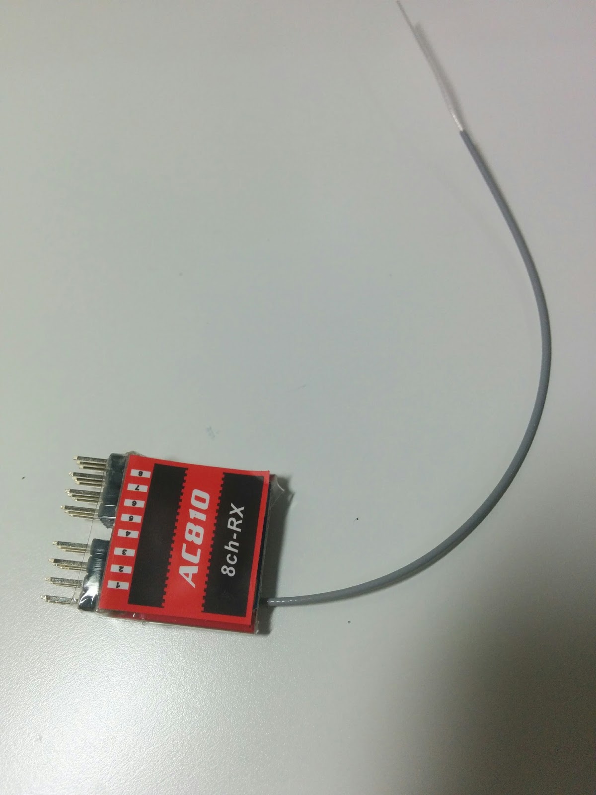
So I bought this AC810 from Taobao for around US$10 plus
shipping, and here it is, small size, weight 5g with all the pins, I later
trimmed out the pins & part of the ‘L’ shape board and it weights less than
3g!
I am new to this quad hobby (less than 1 year), and just
learned that to flash the RX, I need to buy something called USBASP programmer,
and need to use 6 wires to connect some of the pins between the RX and the
USBASP 10pins connector! Anyway, after 1 to 2 days searching and reading from
the web, I managed successfully flashed the latest firmware from the above URL
to the AC810 RX, so I want to share my experience to others who are new to this
hobby. Here are the steps:
1. Prepare the USBASP hardware and wiring:

You can get the USBASP from Banggood, for less than
US$4. Note that it supports either 3.3V
or 5V output, we need 3.3V for this flashing, important!
The one I got is default to 5V, so I need to remove the R5
resistor at the back bottom of the USBASP.
Just use a hot iron to strip it away, like this, in the photo,


you can see the resistor is still attached at one end. I used a multi-meter to check the VCC output
pin just to make sure it is indeed 3.3V, otherwise 5V will fry the RX! So this is important.
There is an excellent site in below URL that talks about how
to use this 10pins USBASP to program AVR chip, from there you will find out
which pins are the required 6 to use (note that the top red colour wire is the
VCC, so this will give you some hints on the orientation of the 10 pins socket
in the diagram)
From above site, I learned the 6 required pins and their
meaning, per below (extracted from the above site)
Pin Name
|
Description
|
Comment
|
MOSI
|
Master Out Slave In
|
This allows the master
device (the USBASP) to send data to the slave device (target AVR being
programmed).
|
MISO
|
Master In Slave Out
|
This allows the slave
device (target AVR being programmed) to send information to the master device
(the USBASP programmer).
|
SCK
|
Serial Clock
|
This is the mutual
clock shared between the master and slave device for synchronized
communication.
|
Reset
|
Target AVR MCU Reset
|
The reset pin for the
AVR chip being programmed must be put in active low in order for programming
to occur.
|
Vcc
|
Power
|
The master and slave
device both need power in order to operate.
|
GND
|
Common Ground
|
The master and slave
device must share a common power ground for operation.
|
To map these pins to the AC810 / F801 DIY Frsky RX, I
learned it from below site:
So here is the complete mapping I wrote down to a piece of
paper for easy reference while doing the wiring. (the AC801 F810 should be AC810 F801 :)


And here are the connected wires. Note that for the reset pin, I did not solder
it to the board; I just used my hand holding it to the reset point while doing
the flashing like above site.
2. Install driver
To use the USBASP, I need to install the USB driver (note
that I am running win7), to do that, use zadig_2.2.exe (from below URL) which
will install the driver while connected the USBASP and select usbasp driver to
install.
for more details visit this link: http://www.fischl.de/usbasp/
(note that I need 2 attempts to install the driver before my
PC can recognize the USBASP device, I don’t know why!)
3. Actual flashing
Get the latest RX firmware (by midelic) from below link, I used FrskyRx_F801_TELEMETRY_PFS_SBUS_240816.hex from below link:
I used the AVR Burn-O-Mat GUI to do the actual flashing,
download from below link. It requires
Java runtime.
Steps:
1.
Click Settings -> AVRDUDE,
a.
set the avrdude.exe & avrdude.conf location
(I’ve avrdude installed already when I installed the eepskye GUI for my Turnigy
XR9 Pro tx radio)
c.
Port set to your connected USB com port or just
usb
2.
In main screen,
a.
set AVR type = ATmega328p
b.
under Flash, select the FrskyRx hex file that
was downloaded from the RC group (ie in
my case, it is FrskyRx_F801_TELEMETRY_PFS_SBUS_240816.hex)
c.
under Flash, click the Write button - - this
will do the actual flashing of the firmware!
It takes around 10 seconds, you will see Reading …. Writing
…. Reading… where … are a few lines of notification of what it was doing, at
the end you will see “avrdude.exe done. Thank you”. Note that during the flash, you must touch
the reset pin against the reset point in the RX board.
There is a youtube video from SeByDocKy on how to flash this
RX as well, but he was using a different GUI.
After flashed the firmware, I get RSSI reading in my 9XR PRO
radio immediately as I have setup a voice warning on RSSI!

I will work on how to get voltage telemetry from the RX next (it
requires soldering 2 resistors into the RX). [see below 20160918 update]
Trimming the RX pins and PCB:
Initially I just cut out the pins and soldered 3 wires into the bottom of the 'L' shape PCB,

but later I saw some photos that people actually cut out the bottom part of the 'L' shape PCB, making this RX even smaller and lighter. So this is exactly what I did :)

After the bottom 'L' part of the PCB is cut out, remember the 8 'S' pins are at the bottom, while on the top, you can see 9 pins instead of 8, all are Vcc+ pins except the middle pin, which is the GND. You can use some clear nail polish as insulator to cover all the Vcc+ pins.
I installed the RX on top of the flight controller board of the QX80, this is what it looks like.


2060919 update:
Adding Voltage Telemetry:
I managed to get voltage telemetry from the RX. Here is the diagram I followed to create the voltage divider and soldered it to channel 8 pin. (diagram from the same "DIY Frsky TX/RX module" RCgroups, and thank you the brilliant work from midelic)

I am using the 10k / 3.3k resistors as advised. Here is my wiring, I grounded to the GND pin on the other side of the AC810.

In my 9XR Pro, I need to set the below screens in order to get the A1 voltage reading.
COM port 2, baudrate 56700

Also in telemetry screen, changed the 1st v value under A1 so that the reported voltage on the right is nearest to your lipo voltage (as measured by a multimeter)

Then you can set up a voice alarm as follows:

Here is a homepage screen that displays both the RSSI and flight voltage. Done! :)


Dear David. Thank you so much for bringing all this information together. This is by far the best source for updating these small receivers. I'm also quite new to the hobby, so this helped me a lot. Greetings. Henri
ReplyDeleteYou're welcome and happy flying :)
Delete